

As a core component of power transmission, the resistance characteristics of 銅バスバー directly determine energy efficiency and system stability. This article analyzes the calculation logic, influencing factors, and engineering optimization strategies of copper busbar resistance through eight core arguments. Combined with temperature gradient data, material comparison tables, and references to international standards, this paper provides electrical engineers with a reference guide that combines theoretical depth and practical value.
導入
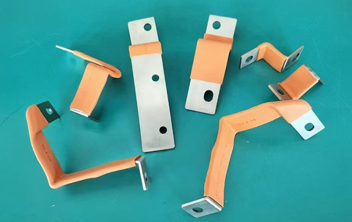
Against the backdrop of the surge in industrial electricity consumption, copper busbars have become the conductor of choice for power transmission and distribution systems due to their high electrical conductivity. However, accurate calculation and optimization of resistance is still a design challenge. According to the International Copper Association, optimizing busbar resistance can reduce energy loss by 5%-15%. In this paper, we will use authoritative data and engineering cases to build a full-dimensional analysis framework for copper busbar resistance.
The formula of copper busbar resistance
a Basic formula: engineering application of the law of resistance
The calculation of copper busbar resistance follows the classical formula:[ R = \rho \frac ]
どこ:
- (R) ): resistance value (Ω)
- ( \rho ): resistivity of copper (( 1.68 \times 10^ \, \Omega \cdot m )) at 20°C)
- (L ): busbar length (m)
- (A ): cross-sectional area (m²)
Case Validation:
A substation uses a 100mm x 10mm cross-section copper busbar with a length of 5 meters; the resistance at 20°C is calculated as:[ R = 1.68 \times 10^ \times \frac = 8.4 \times 10^ \, \Omega ]
(Source: Standard Calculation Manual for Electrical Engineering)
Factors Affecting Copper Busbar Resistance
1. Material purity and processing technology
- Copper content: 99.9% oxygen-free copper resistivity is 3%-5% lower than ordinary copper.
- Annealing treatment: The resistivity of fully annealed copper is about 2% lower than that of hard copper.
2. Quantifying the Effect of Geometric Dimensions
| パラメータ | Resistance Trends | Engineering Optimization Suggestions |
|---|---|---|
| Length increase by 20% | Resistance +20% | Shorten path or lay in sections |
| 50% increase in cross-sectional area | Resistance -33% | Optimized design using width-to-thickness ratio |
3. Non-linear relationship of temperature effects
An increase in temperature leads to an increase in the thermal vibration of copper atoms and a linear increase in resistivity:[ \rhoT = \rho [1 + \alpha (T-20)] ] Where ( \alpha ) is the temperature coefficient of resistance of copper (0.00393/°C).
Temperature-Resistivity Cross Reference
| Temperature (℃) | Resistivity (×10-⁸ Ω-m) |
|---|---|
| 0 | 1.68 |
| 50 | 1.72 |
| 100 | 1.88 |
Special Resistance Problems in Engineering Scenarios
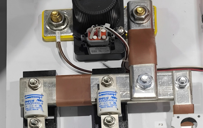
A. Hidden Losses in Contact Resistance
The contact resistance at the connection between the busbar and equipment can be up to 10 times more than the body resistance:
- Influencing factors: surface oxidation (copper oxidation rate accelerates above 40℃), insufficient pressure (recommended contact pressure >15N/mm²).
- Solution: Silver plating (reduces contact resistance by 30%-50%) or use disc spring washers to maintain constant pressure.
B. Skin effect at high frequencies
When the frequency exceeds 1kHz, the current tends to be distributed towards the surface of the conductor, and the equivalent resistance increases significantly:[ R = R \times (1 + 0.005f^) ] (Source of formula: IEC 60287 standard)
Comparison of copper properties with other conductors
| 材料 | 20°C Resistivity (×10-⁸ Ω-m) | Cost Index | 適用可能なシナリオ |
|---|---|---|---|
| Electrolytic Copper | 1.68 | 100 | High Voltage Switchgear |
| Aluminum alloys | 2.82 | 65 | Overhead lines |
| Silver-plated copper | 1.62 | 150 | Precision instrument connections |
Strategies for Reducing Copper Busbar Resistance
- Cross-section optimization: Calculate the optimal cross-section by the economic current density method (recommended value: 2-4A/mm²).
- active cooling: forced air cooling can make the 70 ℃ operating resistance reduced by 18%.
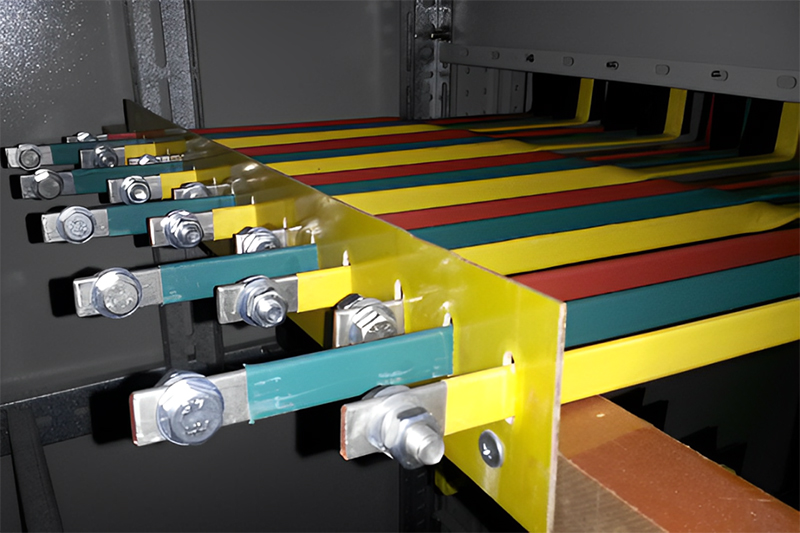
- Segmented insulation: Reduces eddy current losses and increases effective current carrying capacity.
- Surface treatment: chemical passivation treatment to inhibit oxidation (oxidized copper resistivity is 1000 times higher than pure copper).
結論
Accurate control of 銅バスバー resistance is the cornerstone of building an efficient power system. Through the temperature correction model, contact optimization scheme, and material selection comparison explained in this paper, engineers can systematically improve the design level. In the future, with the breakthrough of superconducting material technology (e.g., MgB₂ realizes zero resistance at -253℃), the application scenario of copper busbar may be further expanded, but its cost-effective advantage in the field of room temperature is still difficult to replace.
Related Post
Why can’t a copper busbar and an aluminum busbar be directly connected?
[email protected]2025-12-08T02:54:03+00:0012月 8th, 2025|0 Comments
Introduction Copper busbars and aluminum busbars are the two most commonly used conductive materials in the field of power systems and industrial distribution. Due to differences in cost, resource availability, and technical requirements, they often
How to Prepare for a Big Win at Tez888 Casino
Developer Ismail2025-10-04T21:44:04+00:0010月 4th, 2025|0 Comments
When aiming for a significant payout at Tez888 casino, one crucial step often overlooked is thorough receipt checking and verification. Properly managing your transaction records not only ensures transparency but also plays a vital role
Tips and Tricks for Successful Betting on Bettilt
Developer Ismail2025-08-17T05:29:18+00:008月 17th, 2025|0 Comments
When engaging in online betting, particularly on platforms like bettilt, it's crucial to incorporate strategies such as receipt checking, tax optimization, and thorough verification to maximize your success. These elements ensure that your betting activities

How Do You Calculate the Size of a Copper Busbar?
[email protected]2025-06-06T06:54:57+00:006月 6th, 2025|0 Comments
1. Introduction to Busbar Sizing Accurate copper busbar sizing is vital for secure, dependable, and effective electric circulation. Busbars disperse high currents in switchgear and panelboards. Inappropriate sizing reasons extreme warmth, power loss, voltage
10 Essential Tips for Working with Copper Busbars
[email protected]2025-06-03T06:35:28+00:006月 3rd, 2025|0 Comments
In modern power systems, copper busbars have actually become a core element in power transmission and distribution because of their superb electric conductivity, rust resistance and mechanical strength. As a specialist manufacturer of copper
A Guide to Maintaining Copper Busbars Effectively
[email protected]2025-05-28T06:09:36+00:005月 28th, 2025|0 Comments
As a core component of power transmission systems, copper busbars are an important choice for industry due to their high electrical conductivity, corrosion resistance and mechanical strength. However, the durability of its performance is
お問い合わせ
あらゆるカスタマイズバスバーをお届けします
関連記事
ナム・ラキニア・アーク・トルトル、ネック・ルクタス・ニブ・ディグニッシム、ユー・ヌラ・シット・アメット・マキシムス。

ナム・ラキニア・アーク・トルトル、ネック・ルクタス・ニブ・ディグニッシム、ユー・ヌラ・シット・アメット・マキシムス。
ナム・ラキニア・アーク・トルトル、ネック・ルクタス・ニブ・ディグニッシム、ユー・ヌラ・シット・アメット・マキシムス。