

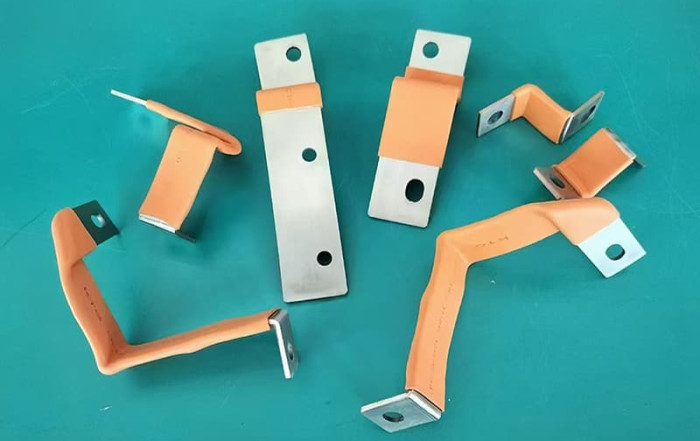
1. Introduction to Busbar Sizing
Accurate koperen busbar sizing is vital for secure, dependable, and effective electric circulation. Busbars disperse high currents in switchgear and panelboards. Inappropriate sizing reasons extreme warmth, power loss, voltage decline, and possible failures like insulation damages or fire. Understanding influencing factors and sizing methods is essential.
2. Essential Sizing Restraints
Busbar existing ability (ampacity) is limited mostly by thermal efficiency (temperature level increase), current capacity, and voltage decrease. Temperature rise is typically one of the most essential, particularly in rooms. Warmth from $I ^ 2R$ losses need to dissipate to keep temperature level within limits.
A simplified ΔT formula is symmetrical to wattage loss and inversely proportional to heat dissipation location. ΔT≈1000×Wattage loss1.1×area in sqcmΔT≈1.1×area in sqcm1000×Wattage loss. This is approximate and doesn’t cover all warmth transfer.
Warm transmission through links decreases temperature level surge in your area. The warm network method evaluates warmth circulation taking into consideration transfer coefficient (α), area (A), thermal resistance (R), and ΔT. High measured ΔT might show outside warmth or lowered dissipation.
For brief circuits, ΔT presumes warm is absorbed by the conductor with negligible transfer throughout the brief period. Trick variables are time ( T), first (Θ1) and max allowable (Θ2) temperature levels, area (A), and RMS existing (I)
Comprehensive versions evaluate steady-state thermal habits, making up current, cross-section, length, product resistivity variation, and get in touch with resistance. Product properties like resistivity (ρa), thermal conductivity (λ), and temperature coefficient (α0) are important. ΔT is inversely proportional to cross-sectional area.
Voltage decrease relies on current and busbar insusceptibility. A/c impedance is greater than DC as a result of regularity impacts like skin and proximity effects.
3. Required Design Criteria
Accurate sizing needs crucial inputs specifying electrical and environmental problems:
- Optimum continuous current: Steady-state operating current.
- Optimum ambient temperature level: Crucial for thermal computations. Greater ambient reduces heat transfer capacity. Specifications like IEC 61439-1 specify restrictions (e.g., +40 ° C max, 24hr avg +35 ° C ).
- Allowed temperature rise: Max acceptable temperature above ambient, defined by criteria (IEC, UL, ANSI) and insulation scores. Examples: ANSI C37.20 enables 65 ° C surge over 40 ° C ambient with silver plating, 30 ° C without. BS 159 permits 50 ° C increase over 35 ° C mean ambient. Ranked existing is set by temperature level increase tests.
Various other specifications:
- Existing kind (AC/DC) and regularity (A/C): Impacts existing circulation.
- Installment configuration: Room, air flow, parallel bars, spacing, alignment impact warm dissipation and present distribution.
- Busbar product residential or commercial properties: Resistivity, conductivity, temperature level coefficient.
- Surface area therapy: Affects radiation warmth dissipation.
- Elevation: May call for derating.
- Short-circuit existing and duration: For mistake stand up to verification.
These specifications guide method option and derating for figuring out needed dimensions.
4. Effect of Setup Setup
Physical arrangement and environment exceptionally affect ampacity and thermal efficiency.
Enclosure/Ventilation: Enclosed busbars have lower ampacity than outdoor because of limited air flow. Ampacity in units is mainly identified by temperature increase examinations (UL, ANSI). Straightforward current thickness rules are unreliable for enclosed systems. Setting up power dissipation have to be within enclosure capacity. Compelled cooling rises ability over natural convection.
Parallel Bars/Derating: Identical bars increase capacity however unequal existing sharing happens as a result of tolerances, connections, and reactance. This calls for derating total ampacity listed below the amount of specific bars. Derating variables increase with more identical bars. Existing ability in $n$ bars is much less than $n$ times one bar’s capability.
Spacing/Orientation: Spacing influences heat transfer and closeness impacts. Increased spacing boosts dissipation and ampacity. Side-by-side setups cool down less effectively than piled.] Maximizing rib spacing/perforations enhances heat transfer. Horizontal bottom surface area air conditioning is less reliable.
Compact/Sandwich Equipments: Encapsulation permits small designs. Close spacing lowers inductance, resistance, voltage drop, and alluring losses.
Various Other Variables: Metallic units (aluminum) lower proximity impacts and unit heating. Elevation requires derating. Poor connections trigger home heating; sufficient contact stress is essential.
A combined condition factor ( K) accounts for influences: variety of bars (k1), surface area (k2), location (k3,k4), air flow ($k5), existing kind (k6). Paint enhances dissipation (k2= 1.15). Place factors differ (edge-mounted k3= 1, base-mounted k3= 0.95 for one).
5. Influence of AC vs. DC Applications
Current kind, especially air conditioning frequency, influences current circulation by means of skin and proximity effects, enhancing efficient AC resistance and losses.
Skin Effect: air conditioning existing concentrates near the surface, reducing effective area. More obvious at greater regularities. Skin deepness (current thickness goes down to ~ 37%) is ~ 8.5 mm for copper at 50 Hz. This limits efficient busbar density listed below 10 mm. Factors ( ys) and empirical formulas estimate added loss.
Proximity Impact: Electromagnetic fields from close-by conductors generate eddy currents, crowding present in areas. Boosts efficient a/c resistance and losses, especially with close spacing. Power loss can boost quicker than location.
The distance factor (K=RAC/RDC) evaluates resistance boost. Decreased spacing rises distance result and losses.
Integrated Impact/Mitigation: Both effects enhance air conditioner resistance, I2R losses, and voltage decline. Significant for high currents (> 2000A) and long systems.] Small loss increases have financial influence. Unbalanced reactance triggers voltage inequalities and electrodynamic forces
Reduction techniques:
- Boost Spacing: Decreases magnetic field influence.
- Interleaving/Transposition: Adjusts existing amongst identical bars.
- Busbar Geometry: Numerous thinner bars manage skin impact far better than one thick bar.
- Enclosures: Metallic rooms (aluminum) reduce closeness impacts.
Mixed effect is accounted for by a correction factor (S) = skin aspect (Sk) * closeness aspect (Sp).
6. Calculation Methods and Requirements
Sizing entails methodologies assisted by standards for safety and reliability. Techniques calculate called for area based upon allowable temperature increase for continuous current, taking into consideration environment and a/c impacts. This is often repetitive [15]
Key criteria:
- IEC 61439 (Low-Voltage Switchgear): Important for busbars in settings up. IEC 61439-2 covers PSC-Assemblies, needing existing scores meet information sheets at specified ambient. Ranked existing should be continual after derating; major busbars rated for small present over size.
- Temperature Increase Verification: Techniques include kind testing, contrast, or computation.
- Estimation Confirmation: Permitted for settings up ≤1600 A making use of criteria like IEC TR 60890. Requires circuit rated current ≥ style existing. Estimation limits apply (≤1600 A, elements derated to 80%). For solitary compartments ≤ 630 A complete supply, estimation is permitted if loss data is offered, losses are even, and circuit currents ≤ 80 of cost-free air rating.
- Ranked Diversity Factor (RDF): 1.0 for primary straight busbars in IEC 61439-2 tests/calculations.
Minimum Cross-Section: Specifications might specify minimal area (e.g., 125% of needed current score). - Power Dissipation: Overall setting up loss have to be within unit capacity.
- UL and ANSI Standards: Utilized in The United States And Canada. Sizing usually by temperature level rise examinations. Eaton utilizes UL/ANSI 65 ° C rise over 40 ° C ambient.
- NEMA Criteria: Guidelines for design/testing.
- Copper Growth Organization (CDA): Resources include streamlined solutions, visual methods, and ampacity tables.
- Empirical Data/Formulas: Made use of when simulation isn’t viable. Use carefully and confirm.
- Short-Circuit Calculations: Specifications offer approaches for thermal/mechanical hold up against.
Technique option depends upon system complexity, precision needed, information schedule, and regulating standards. Facility systems or those going beyond computation limitations need physical kind screening.
7. Selecting Physical Dimensions
After figuring out needed cross-sectional area, select sensible size and density. Think about basic sizes, mechanical toughness, thermal performance, and current circulation.
Copper busbars been available in standard rectangular dimensions. Select measurements providing the calculated location (e.g., 500 mm two location can be 50×10 mm or numerous parallel bars).
Factors for dimension option:
- Basic Dimensions: Simplifies purchase, minimizes cost.
- Mechanical Stamina: Need to stand up to weight, installing, and short-circuit electrodynamic forces. Measurements and spacing affect rigidness.
- Thermal Efficiency: Surface area is crucial for warmth dissipation. Broader, thinner bars have larger surface area for far better air conditioning and
- higher ampacity.
- Existing Circulation (AC): Skin/proximity effects affect circulation. Several thinner bars can improve AC efficiency. Spacing parallel bars manages closeness effects.
- Connection Requirements: Dimensions must fit devices terminals. Ample area for bolted connections makes certain low call resistance.
- Area Restraints: Measurements should fit within the enclosure/installation room. Portable systems lessen area.
Existing density is a harsh check. Permissible thickness is higher for smaller bars. Rough estimate for copper in still air is ~ 2 A/mm TWO.
Final dimension option balances electrical/thermal efficiency, mechanical demands, space, price, and manufacturability.
8. Advanced Sizing and Evaluation Devices
Advanced software provides comprehensive analysis and optimization for facility systems, high currents, and transients using FEA and CFD.
CENOS BBH: Coupled electro-magnetic, thermal, architectural analysis for AC/DC busbars. Imitates existing distribution, Joule home heating, hotspots, voltage decline, thermal tension. Enables style modification and optimization. Sustains steady-state and short-term analysis.
Ansys: Pairs electromagnetic (Maxwell) and thermal (Icepak) simulation.Beneficial for inverter busbars. Maxwell’s short-term solver locates ohmic loss circulation (consisting of air conditioning effects), mapped to Icepak for thermal evaluation .
EMWorks: Electrothermal simulation focusing on resisting warm generation. Electric Transmission solver incorporated with thermal analysis simulates area, present density, possibility, temperature, heat change. Needs product homes, inputs (convection, ambient), and meshing.
JMAG-Designer: Consists of busbar thermal stress analysis. Predicts temperature level rise and variation from magnetic field evaluation heat generation.
These devices enable in-depth analysis past hand-operated approaches:
- Design complicated geometries/arrangements.
- Make up non-uniform air conditioner present distribution.
- Imitate transients (brief circuits, tons modifications).
- Evaluate cooling down approaches.
- Anticipate temperature distribution/hotspots.
- Review mechanical anxieties (thermal expansion, electromagnetic forces).
- Optimize dimensions, spacing, materials.
They require specific knowledge however refine styles, guarantee compliance, and push capacity restrictions. CFD assesses temperature level increase under numerous conditions. Analytical formulas automate ampacity/heat transfer coefficient. Simulation can complement or replace physical testing during style.
Related Post
Why can’t a copper busbar and an aluminum busbar be directly connected?
[email protected]2025-12-08T02:54:03+00:00december 8th, 2025|0 Comments
Introduction Copper busbars and aluminum busbars are the two most commonly used conductive materials in the field of power systems and industrial distribution. Due to differences in cost, resource availability, and technical requirements, they often
How to Prepare for a Big Win at Tez888 Casino
Developer Ismail2025-10-04T21:44:04+00:00oktober 4th, 2025|0 Comments
When aiming for a significant payout at Tez888 casino, one crucial step often overlooked is thorough receipt checking and verification. Properly managing your transaction records not only ensures transparency but also plays a vital role
Tips and Tricks for Successful Betting on Bettilt
Developer Ismail2025-08-17T05:29:18+00:00augustus 17th, 2025|0 Comments
When engaging in online betting, particularly on platforms like bettilt, it's crucial to incorporate strategies such as receipt checking, tax optimization, and thorough verification to maximize your success. These elements ensure that your betting activities

How Do You Calculate the Size of a Copper Busbar?
[email protected]2025-06-06T06:54:57+00:00juni 6th, 2025|0 Comments
1. Introduction to Busbar Sizing Accurate copper busbar sizing is vital for secure, dependable, and effective electric circulation. Busbars disperse high currents in switchgear and panelboards. Inappropriate sizing reasons extreme warmth, power loss, voltage
10 Essential Tips for Working with Copper Busbars
[email protected]2025-06-03T06:35:28+00:00juni 3rd, 2025|0 Comments
In modern power systems, copper busbars have actually become a core element in power transmission and distribution because of their superb electric conductivity, rust resistance and mechanical strength. As a specialist manufacturer of copper
A Guide to Maintaining Copper Busbars Effectively
[email protected]2025-05-28T06:09:36+00:00mei 28th, 2025|0 Comments
As a core component of power transmission systems, copper busbars are an important choice for industry due to their high electrical conductivity, corrosion resistance and mechanical strength. However, the durability of its performance is
Neem contact op
Wij leveren alle aangepaste busbars
Gerelateerde berichten

Introduction Copper busbars and aluminum busbars are the two most commonly used conductive materials in the field of power systems and industrial distribution. Due to differences in cost, resource availability, and technical requirements, they often need to be connected and used in practical applications. However, directly connecting copper aluminum busbars can pose serious safety hazards.
When aiming for a significant payout at Tez888 casino, one crucial step often overlooked is thorough receipt checking and verification. Properly managing your transaction records not only ensures transparency but also plays a vital role in tax optimization. Understanding the legal framework surrounding gambling winnings and maintaining accurate documentation will help you navigate potential audits
-
When engaging in online betting, particularly on platforms like bettilt, it’s crucial to incorporate strategies such as receipt checking, tax optimization, and thorough verification to maximize your success. These elements ensure that your betting activities remain transparent, compliant with legal requirements, and financially efficient. By focusing on these areas, bettors can safeguard their investments and