

Introduction
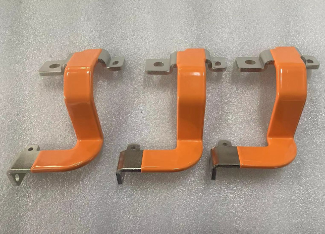
As the core conductive element of the circuit system, the copper busbar assumes the key functions of current transmission and equipment connection. Its rounded corners are designed to avoid tip discharge, and it is suitable for high-voltage power distribution systems (e.g., 10 kV opening and closing stations) and low-voltage complete sets of equipment. The conductivity, mechanical strength, and corrosion resistance of the copper busbar directly affect the safety and stability of the electrical system.
How is the Design of copper busbars?
a. Design planning
- Program development: based on the design drawings and production task orders to determine the direction, size, and bending form of the busbar, giving priority to the use of the remaining short copper busbar to reduce costs.
- Material selection:
- Main busbar: select specifications (e.g., T2 purple copper or H62 brass) according to the drawings, and the branch busbar defaults to the same material as the main circuit.
- Grounding busbar: The PE line of the low-voltage distribution device should meet the requirements of current-carrying capacity; the cross-section of the high-voltage grounding busbar ≥ 30 mm² and over the door line ≥ 4 mm².
- Material inspection: Check the surface finish of the copper busbar for no cracks and deformation; check the certificate of conformity and material report.
b. Tools and equipment
- Necessary tools: busbar processing machine, torque wrench, drilling machine, heat-shrinkable sleeve cutting tool.
- Auxiliary materials: power composite grease, lock nut, anti-oxidation petroleum jelly (for lubrication at bends).
3. How is the production process?
A. Core specification
- Electrical clearance and creepage distance: electrical clearance of low voltage switchgear ≥15mm, creepage distance ≥20mm.
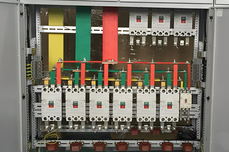
- Phase sequence arrangement:
- AC system: up and down arrangement is A (yellow), B (green), and C (red); horizontal arrangement is A→C from the back of the disk to the surface of the disk.
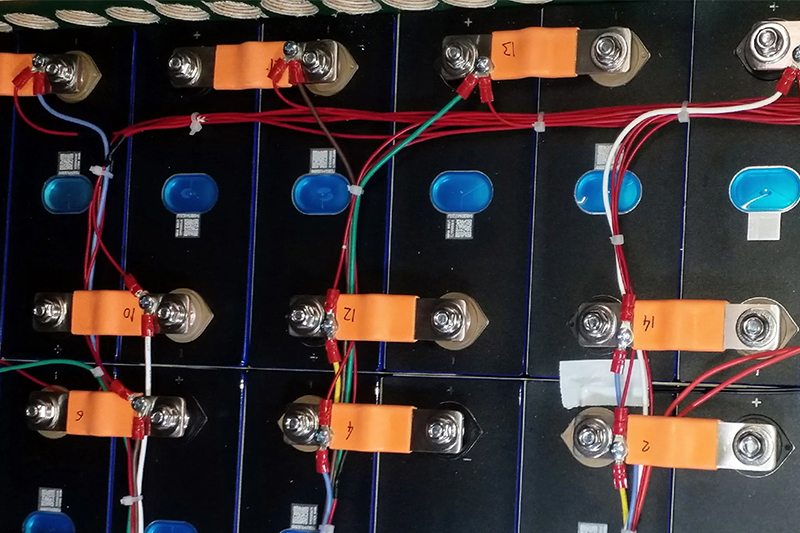
- DC system: positive pole at the back/left, negative pole at the front/right.
B. Production process
- Straightening and cutting:
- Straighten with a busbar leveling machine; vertical bending ≤ 2 mm/m, flat bending ≤ 3 mm/m, and the cut-off surface is flat and burr-free.
- Punching hole diameter should be 0.5-1mm larger than the bolt, with a hole distance error of ± 0.5mm. 2.
- Bending process:
- Avoid right-angle bending; using the cold bending process, the minimum bending radius is according to the thickness of the copper busbar (such as a 50 × 5mm copper busbar flat bending radius ≥ 2 times the thickness).
- Twisted 90 °, the length of the twisted part should be 2.5-5 times the width of the busbar.
- Surface treatment:
- The contact surface needs to be polished to remove the oxide layer; copper busbar section reduction ≤ 3%, aluminum busbar ≤ 5%. The lap surface should be coated with power composite grease.
- The overlap surface coated with power composite grease and the silver-plated surface prohibit filing.
How is the Installation of copper bus bars?
1. Busbar and equipment connection
- Bolt fastening:
- Use torque wrenches to tighten according to the standard (such as M12 bolts need 31.4-39.2 N-m); the bolt exposes the nut 2-3 buckles.
- Horizontal installation of the bolt from the bottom up through to avoid the formation of a closed magnetic circuit.
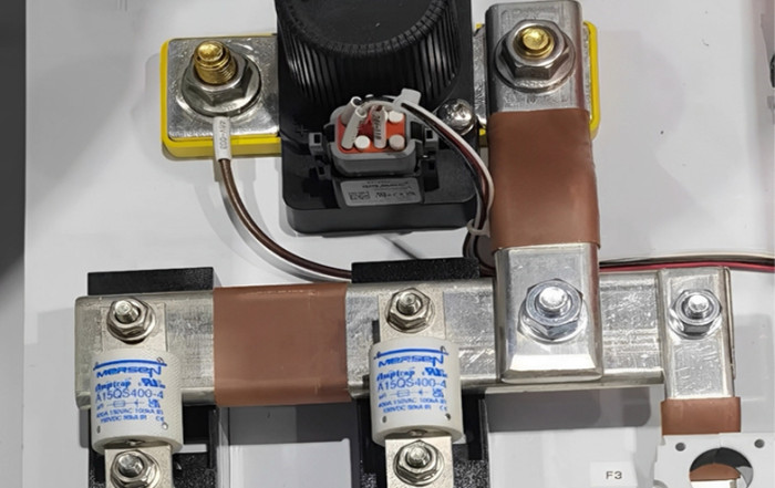
- Special connection:
- Screw terminals need to add copper tin-lined flat washers and prohibit the use of spring washers.
- Copper and aluminum connections need to use transition plates in humid environments, with copper ends tin-lined.
2. Heat Shrink Treatment and Marking
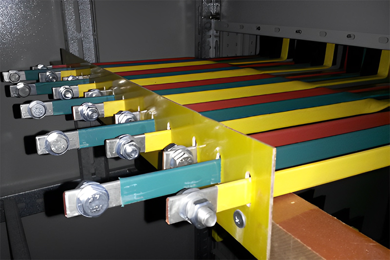
- Heat-shrinkable tubing:
- Select the sleeve according to the phase color (yellow/green/red); the bent tube needs to be preheated and then straightened, with a heating
- temperature of 600-650℃.
- Cutting holes need to be positioned with sleeves to avoid scratching the copper busbar .
- Marking requirements:
- Zero line (N) and ground line (PE) paste Φ20/30mm marking; outdoor busbar needs insulation heat-shrink protection.
3. Installation acceptance
- Accuracy check:
- Vertical installation error ≤2 mm/full length ≤5mm; horizontal error ≤3 mm/full length ≤10mm.
- The distance between support points is ≤2.5m, and insulators are fixed without extra stress.
- Safety test:
- Ground resistance ≤ 0.1 Ω, contact resistance of spanning point ≤ 1.2 times the busbar resistance of the same length.
- Voltage withstand test: a 10 kV system needs to pass a 42 kV/1 min industrial frequency voltage withstand.
Special Scenario Handling
- Fire protection and shockproof: a fireproof partition should be installed when crossing the firewall, and a waterproof platform and anti-vibration bracket should be set at the floor.
- Outdoor protection: when the grounded copper busbar is <1.8m from the ground in the non-electrical shaft, it is necessary to install a protective cover.
- High-current scenario: parallel copper busbar spacing ≥ thickness to avoid local overheating.
Common Problems and Optimization
- Deformation control: a consistency check is required for multi-piece bus bar bending to avoid installation stress.
- Anti-corrosion measures: tin-plated or silver-plated treatment of contact surfaces; bracket using the hot-dip galvanizing process.
- Waste utilization: short copper busbars are prioritized for branch circuits to reduce material waste.
Through the above steps, you can systematically complete the whole process from design to installation of copper busbars, taking into account the electrical performance and process aesthetics. In practice, we need to strictly follow the industry standards (such as GB5585.1 and GB7251) and flexibly adjust with the on-site environment.
Related Post
Why can’t a copper busbar and an aluminum busbar be directly connected?
[email protected]2025-12-08T02:54:03+00:00December 8th, 2025|0 Comments
Introduction Copper busbars and aluminum busbars are the two most commonly used conductive materials in the field of power systems and industrial distribution. Due to differences in cost, resource availability, and technical requirements, they often
How to Prepare for a Big Win at Tez888 Casino
Developer Ismail2025-10-04T21:44:04+00:00October 4th, 2025|0 Comments
When aiming for a significant payout at Tez888 casino, one crucial step often overlooked is thorough receipt checking and verification. Properly managing your transaction records not only ensures transparency but also plays a vital role
Tips and Tricks for Successful Betting on Bettilt
Developer Ismail2025-08-17T05:29:18+00:00August 17th, 2025|0 Comments
When engaging in online betting, particularly on platforms like bettilt, it's crucial to incorporate strategies such as receipt checking, tax optimization, and thorough verification to maximize your success. These elements ensure that your betting activities

How Do You Calculate the Size of a Copper Busbar?
[email protected]2025-06-06T06:54:57+00:00June 6th, 2025|0 Comments
1. Introduction to Busbar Sizing Accurate copper busbar sizing is vital for secure, dependable, and effective electric circulation. Busbars disperse high currents in switchgear and panelboards. Inappropriate sizing reasons extreme warmth, power loss, voltage
10 Essential Tips for Working with Copper Busbars
[email protected]2025-06-03T06:35:28+00:00June 3rd, 2025|0 Comments
In modern power systems, copper busbars have actually become a core element in power transmission and distribution because of their superb electric conductivity, rust resistance and mechanical strength. As a specialist manufacturer of copper
A Guide to Maintaining Copper Busbars Effectively
[email protected]2025-05-28T06:09:36+00:00May 28th, 2025|0 Comments
As a core component of power transmission systems, copper busbars are an important choice for industry due to their high electrical conductivity, corrosion resistance and mechanical strength. However, the durability of its performance is
Get IN TOUCH
We Deliver Any Customize Busbars
Related Posts
Nam lacinia arcu tortor, nec luctus nibh dignissim eu nulla sit amet maximus.

Nam lacinia arcu tortor, nec luctus nibh dignissim eu nulla sit amet maximus.
Nam lacinia arcu tortor, nec luctus nibh dignissim eu nulla sit amet maximus.
Nam lacinia arcu tortor, nec luctus nibh dignissim eu nulla sit amet maximus.